SPONSORED
Cummins - Branded Feature
Specifying the Right Transfer Switch
Cummins
Transfer switch equipment is available in a variety of types, with a wide array of features. Selecting the appropriate transfer switch for a specific application requires a clear understanding of site needs and switch options. This paper discusses the key elements that must be considered when specifying a transfer switch, so that a more informed selection can be made.
Transfer switches are vital! They are 3rd party certified and at the heart of an emergency power system, providing a dependable power transfer between two power sources (a utility and an emergency standby generator, for example) and facility loads. When the normal power source fails, transfer switches detect the loss of power, send a start signal to the standby generator and then connect the generator to facility loads when the generator has reached proper voltage and frequency. When utility power is restored, the transfer switch returns the load from the emergency power source to the normal one.
In cases of utility failure when the emergency power source is not operating, power to facility loads will be lost for a period of approximately 10 seconds while the generator set starts — unless there is an Uninterruptible Power Supply (UPS) serving loads in the system to bridge the power gap while the generator set starts, reaches the proper voltage and frequency, and the automatic transfer switch transfers.
Considerations when selecting a transfer switch
When specifying a transfer switch for a power system, several factors impact the selection of the switch. Some of these factors are (along with some examples):
- Codes and standards (UL, CSA, NFPA, NEMA, IBC, OSHPD)
- Application (utility-to-generator, generator-togenerator, utility-to-utility)
- Transition type (open, closed, non-automatic)
- Switch positions (2-positions, 3-positions)
- Number of poles (3-pole, 4-pole)
- Separately derived or non-separately derived
- Service-entrance or non-service-entrance
- Switch type (transfer switch, bypass isolation switch)
- Voltage and frequency (600VAC, 480VAC/50Hz, 60Hz)
- Current rating
- Fault current capability (WCR*)
- Short-time fault current capability (WCR*)
- Selective coordination (WCR & listed OCPD**)
- Cable lugs and entry requirements (compression/mechanical, top/bottom entry)
- Enclosures (NEMA Type 1, 3R, 4, 4x, 12)
Codes and Standards
Transfer switches are designed to meet the leading testing requirements specified by UL 1008 “Standard for Safety - Transfer Switch Equipment.” UL 1008 specifies robust and rigorous testing requirements for verifying manufacturer ratings and ensure reliability and durability. UL 1008 is harmonized with the Canadian standard CSA C22.2 No.178.1. Any transfer switch product listed as such is suitable for use in any application in North America. Transfer switch products without these listing can be challenged in some marketplaces and applications.
Transfer switches are applied in a variety of applications that typically fall into one of four categories defined by the National Electrical Code® (NFPA 70®): emergency systems, legally required systems, optional standby systems, and critical operations power systems. Understanding those categories is important, as they play a critical role in determining what kind of transfer switch you require.
- Emergency systems (Article 700): Automatically supply, distribute, and control electricity used by systems essential to life safety during fires and other disasters.
They include fire detectors, alarms, emergency lights, elevators, fire pumps, public safety communication systems
- Legally required systems (Article 701): Automatically supply power to a selected set of regulated loads not classified as emergency systems when normal power is unavailable. They serve critical heating, refrigeration, communication, ventilation, and smoke removal
- Optional standby systems (Article 702): Supply power to loads with no direct bearing on health or life safety, and are not required to function automatically during power failures
- Critical operations power systems
(Article 708): Supply, distribute, and control electricity in designated critical areas when a normal power source fails. They include HVAC, fire alarm, security, communication, signaling, and other services in facilities that a government agency has deemed important to national security, the economy, or public health and safety
Another standard that impacts the selection of the transfer switch is NFPA 110® Standard for
Emergency and Standby Power Systems. The intent of NFPA 110® is to achieve maximum system
reliability. It covers installation, maintenance, operation, and testing requirements as they
pertain to the performance of the Emergency Power Supply System (EPSS). The requirements cover the performance of emergency and standby power systems providing an alternate source of electrical power to loads in buildings and facilities if the primary power source fails. The standard differentiates systems by Class, Type, and Level as follows:
- Class: The class defines the minimum time, in hours, for which the EPSS is designed to operate at its rated load without being refueled or recharged.
- Type: The type defines the maximum time, in seconds, that the EPSS will permit the load terminals of the transfer switch to be without acceptable electrical power
- Level: Level 1 and Level 2:
- Level 1 systems are installed where a failure of backup power could result in loss of human life or serious injuries.
- Level 2 systems serve systems and equipment that are “less critical” to human life and safety.
Therefore, a system requirement specifying NFPA 110®, Level 1, Type 10 for power system cannot be met with a manual transfer switch and an automatic transfer switch must be selected.
The additional codes to pay attention to are NFPA 70® Article 517, NFPA 99® for Healthcare, and OSHPD (Office of Statewide Health Planning and Development – Healthcare in California
which also include a seismic element). These standards call for a UL1008 automatic transfer switch for use in emergency systems and some require a bypass isolation transfer switch.
The International Building Code (IBC®) is another
code to consider when selecting and applying a
transfer switch in the power system. It is important
for standby power systems to function after a
catastrophic event, such as a hurricane, tornado,
or an earthquake. IBC® requires that critical
equipment, such as on-site power systems that
power critical branches such as hospitals, police
and fire stations, emergency shelters, power plants,
airports, government facilities, and communications
and operations centers, may need to endure higher
physical shocks and multi-axis accelerations in
certain areas of the United States, including those
generated near the San Andreas Fault in California.
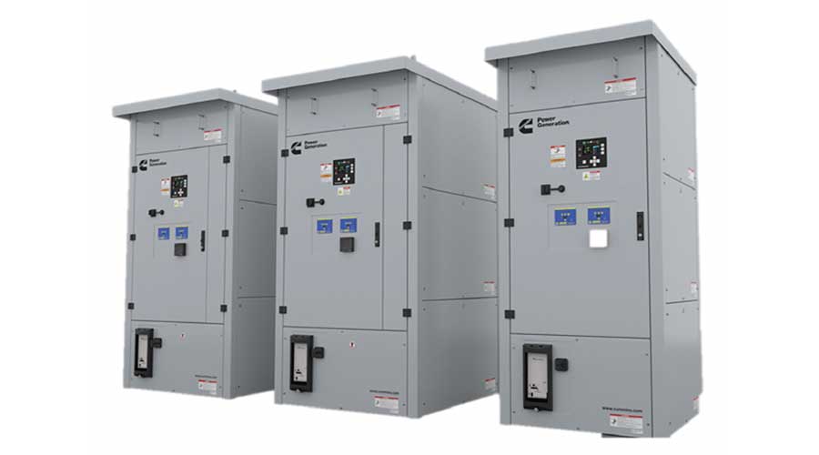
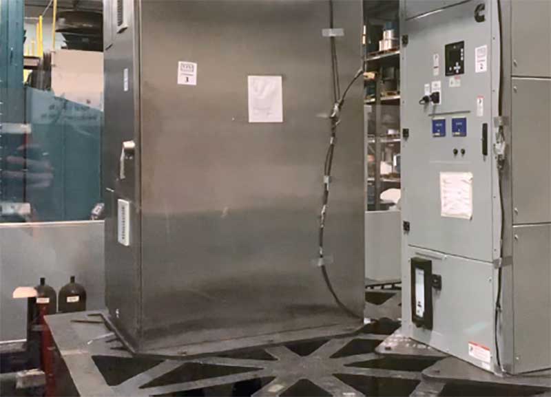
All of the Cummins PowerCommand® X-Series
transfer switches are certified to IBC 2018, which
requires strenuous testing of the assembled
product to verify its ability to survive seismic events.
A variety of arrangements are available utilizing two power sources and three power sources when applying a
transfer switch in a power system:.
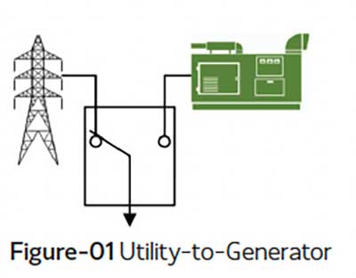
- Utility-to-generator
The most common application and it is typically referred to as
emergency standby generator system. The transfer switch
configuration includes a utility feed and a generator set for normal
and emergency power sources (see Figure-01).
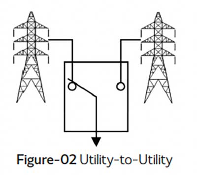
- Utility-to-utility:
In this configuration two utility sources provide redundancy in the
distribution system and allows for quick restoration of service to the
load if one utility source fails. The two sources can be independent
of each other, requiring the public utility company to provide dual
electric services, or they can originate from a single electric service
that is distributed through redundant paths within the facility (see
Figure-02).
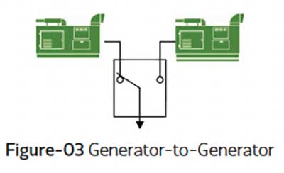
- Generator-to-generator:
The common use case is a prime power application, often at remote
installations. In such cases, the generator may be required to provide
continuous power to the facility loads. To equally share run-time,
source power is periodically swapped between the generator sets via
the transfer switch smart controls (see Figure-03).
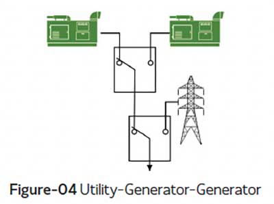
- Utility-generator-generator:
(also known as three power source)
Critical facilities with an emergency standby generator system will
often include provisions for a second generator connection to serve
as a redundant emergency backup that can be used during periods
of inclement weather, or when scheduled maintenance is being
performed on the first generator (see Figure-04).
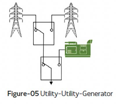
- Utility-utility-generator:
(also known as three power source)
This configuration expands on the redundancy provided by a dual
utility arrangement and includes an emergency standby generator
source (see Figure-05).
Transition type
Transfer switches transition facility loads between
two sources. The way the transition takes place
is known as the transition type. There are three
transition types discussed here: Automatic open
transition, Automatic hard-closed transition, and
Non-automatic transition
Automatic open transition:
Open-transition transfer switches provide a “break-before-make” switching action. They are specifically designed to transfer power between utility and onsite power systems. The connection to one source is opened before the connection to the second source is closed. Mechanical interlocks that positively prevent interconnection of sources are commonly used. Some manufacturers include electrical interlocks in addition to the mechanical interlocks. Open-transition transfer switches are the most commonly used type of transfer switch and are used in all types of applications. By design, they neither require nor allow generator set paralleling with the utility service.
There are three types of open transition: opendelayed, open-fast-transition sync, or open-fast-transition no sync.
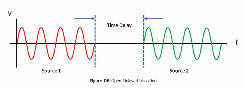
- Open-delayed transition
In an open-delayed transition, the transfer
switch pauses or stops in intermediate position for a pre-set amount of time disconnecting the load from both sources before connecting to the other available source (see Figure-06). Open-delayed transition requires a three-position transfer switch mechanism which is discussed in the next section.
The delay typically lasts a specific, pre-set amount of time. That time delay should be set to allow the voltage generated by the load to decay to a safe level before connecting to the available source. NEMA MG-1 recommends a delay of 1.5x Motor Open Circuit Time Constant. That brings the voltage generated by the load to 22% of nominal. Typical application for this kind of transition is stored energy loads such as inductive motors or MRI machines.
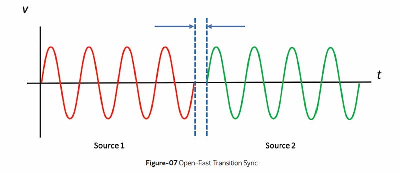
- Open-fast-transition sync:
This transition mode is also known as in-phase transition. In this transition mode, the transfer switch control uses built-in sophisticated algorithm to execute an open transition at the precise moment the normal and emergency power sources are synchronized phase, voltage, and frequency (see Figure-07). Transfer switch controls don’t include active synchronizers. The synchronizers are typically part of the generator integrated control.
Open-Fast-Transition Sync are typically completed in 100ms or less and there are no intentional time delays configured for this mode of transfer. Typical applications for this mode are small inductive loads less than 20hp and resistive loads.
Some transfer switch OEMs such as Cummins include a back-up if synchronization between the two sources doesn’t occur within a pre-set time span. In that event the switch control defaults to an opendelayed transition.
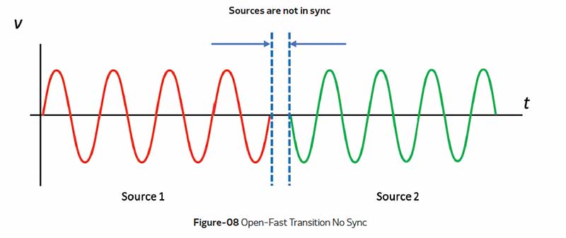
- Open-fast-transition no sync:
In this transition mode, there are no intentional time delays and no need to wait for the sources to be
synchronized before transferring (see Figure-08). Open-Fast-Transition No Sync are typically completed in 100ms or less. Typical applications for this mode are resistive loads.
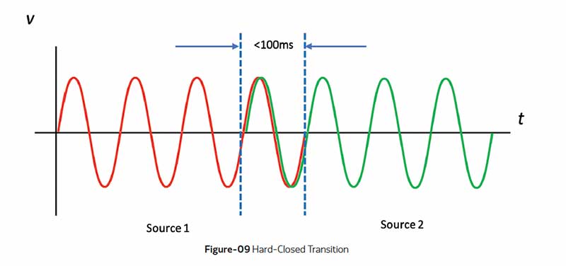
Automatic hard-closed transition:
Closed-transition transfer switches provide a “make-before-break” switching action and utilize a momentary paralleling of both sources (<100ms) during the transfer period, when both sources are available. Both sources must be synchronized (phase, voltage, and frequency) before momentary paralleling them (see Figure-09). Closed transition transfer switches do not include mechanical nor electrical interlocking of sources. Since there is no gap between disconnecting and connecting sources, downstream loads receive continuous power throughout the transfer process.
Some utilities require closed transitions to comply with interconnect requirements aimed at preserving power quality and protecting utility service personnel and equipment. In some cases, this can require the inclusion of protective relays in the electrical circuit such as:
- 62PL Parallel Timer (a timer relay that is independent and external to the transfer switch control which disconnects the site from the utility service if it does not disconnect as designed)
- 32R Reverse Power (directional power relay which disconnects the site from the utility service if power flows into the utility)
- 86LO Lockout (an electromechanical relay which latches its output contacts and prevents reconnection to the utility without intervention from the service supplier)
Always verify local service requirements when providing closed transition transfer switches for an application.
Non-automatic transition:
This transition mode also provides “break-before-make” switching action. The transfer between sources is manually initiated by an operator. All the time delays (transfer, re-transfer, elevator, program transition) and control protection are still active in this mode. The advantage of this mode is that the operators are in complete command of transfer initiation. But this advantage can be a disadvantage in some applications since an operator must be present to initiate a transfer. Also, in this transition mode, there’s neither support for openfast-transition sync (in-phase) nor closed transitions.
It is important to note that non-automatic is not the same as Manual Transfer Switch (MTS). Manual switches are manually controlled and require direct operation by a person to transfer the load. This operation is through a lever or a handle; the switch does not have electrically actuated solenoids, contactors, nor motors. The actual contact mechanisms are operated using spring energy in order to achieve a “quick” make or break of the current carrying contacts. These switches do not have monitoring capability for the power sources. Also, they contain a very rudimentary or no control system.
The NEC® requires automatic transfer switches for Emergency, Legally Required, and Critical Operation Power (Articles: 700/701/708). Manual and Non-Automatic are not permitted.
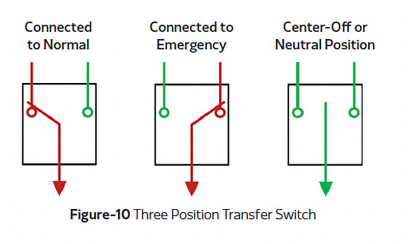
Switch positions
Switch position refers to which source the load is connected. In a 2-position switch, the load is either connected to the normal source or the emergency source. For residential applications, a 2-position transfer switch is a very economical solution.
In a 3-position switch, the load is either connected to the normal source or the emergency source, or it can be in a middle position known as center-off position (see Figure-10). The center-off position is also known as the neutral position. In the center-off position or neutral position, the load isn’t connected to either source. The applications for a 3-position switch are delayed-transition and load shedding. For example, if the load is connected to the emergency source and an overload condition occurs, the generator set control senses that overload condition, then sends a signal to the transfer switch causing it to shed and move to the neutral position. The load shed signal may come from the generator set control or in more complex operations the signal may come from a system level control. The advantage of a 3-position switch is disconnecting the load from the emergency source and staying in center off position. It is not recommended to shed load to a deenergized utility source.
Load shed maybe required by code. NEC® 2020 700.4 (C) allows the alternate power source to supply emergency, legally required, and optional system loads where the source has adequate capacity or where automatic selective load shed is provided as needed to ensure adequate power.
Number of poles
Transfer switches are offered in two configurations: a 3-pole (the mechanism switches the three phase poles A, B, and C. The neutral is solid) and 4-pole (the
mechanism switches the three phase poles A, B, C, and the neutral).
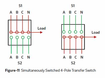
There are two methods of switching the neutral: simultaneous switching and overlapping neutral switching. With simultaneous switching, offered on Cummins switches, the neutral pole is mounted on a common crossbar with the phase poles, and thus, is switched at the same time as the phase conductors in a break-before-make action (see Figure-11). The grounded neutrals of the two power sources are not connected, even momentarily.
With overlapping switching, the neutral pole is momentarily closed to the grounded neutrals of both power sources in a make-before-break action. A temporary solid neutral connection is created with multiple grounds. Neutral current has, therefore, two paths of return to the source during the overlapping make-before-break switching action and a nuisance trip could result when no ground fault exists.
Overlapping neutral transfer switches have inherent failure modes which don’t exist in a simultaneously switched neutral product. Specifically, because the neutral pole operates independently of the phase poles, it could fail to transfer completely when the phase poles transfer. Two effects of this failure mode are that the neutral pole could be left disconnected
from both sources creating a floating neutral condition, and the neutral pole could be left connected to both sources creating two neutral to ground connections with the potential for ground loops and incorrect earth fault detection. Even with a properly functioning neutral pole there will be a period during transfer when two neutral to ground connections will exist.
To determine which configuration (3-Pole or 4-Poles) to select, attention must be paid to
the system grounding scheme and ground fault protection requirements. If ground fault detection is required on either source, a 4-pole transfer switch is necessary in most cases. Per NEC® 230.95 Ground Fault Protection (GFP) of equipment is required at the service disconnect (utility breaker) for systems with all of the following:
- Solidly grounded wye electrical service
- More than 150 volts to ground (277/480 or
347/600VAC)
- Over current device rating of 1000A or more
NEC® 700.6 (D) and 701.6 (D) requires Ground Fault
Indication (GFI) at the emergency source.
Ground fault sensing depends on being able to sense
ground fault current. To accurately sense ground fault
current, it must return to its source on a known path
relative to ground fault current transformers (CTs). In
basic emergency standby systems there are two rules
to follow to meet these requirements:
- There can only be one neutral/ground connection
on any neutral bus at one time
- Ground fault sensors (the CTs) must be
downstream (or on the load side) of the bonding
connection
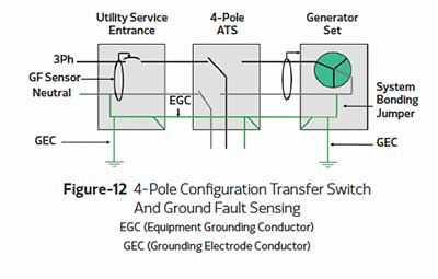
To meet both rules when connected to either the
normal or the emergency source, the neutral must be
switched using a 4-pole transfer switch (see Figure-12).
Separately derived or non-separately derived
The NEC® defines separately derived systems as “An electrical source, other than a service, having no direct
connection(s) to circuit conductors of any other electrical source other than those established by grounding and
bonding connections”. NEC Section 250.30(A)(1) requires separately derived systems to have a system bonding
jumper connected between the generator frame and the grounded circuit conductor (neutral).
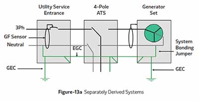
A switched neutral pole as shown in Figure-13a (refer to the previous section: Number of Poles) is used in
applications where it is necessary for accurate sensing of ground fault current. When used, the on-site
generator set is a separately derived system. Where the transfer equipment includes a switched neutral pole
and the generator is a separately derived system, its neutral must be bonded to an effective ground.
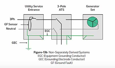
In the system shown in Figure-13b, the neutral conductor is grounded at the service equipment. Ground Fault
Protection (GFP) for equipment may be added to the normal service equipment. The only path for ground fault
current is on the grounding conductor outside of the GFP sensors. The generator neutral is not bonded to
ground, because to do so would create multiple ground fault current paths; one of which would be through the
sensor, the other outside the sensor.
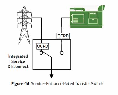
Service-entrance and
non-service-entrance
The National Electric Code requires a way for
disconnecting the electrical service where it enters
a building. Service-entrance rated transfer switches
typically include a circuit breaker on the normal side
which provides for overcurrent protection and a service
disconnect means (see Figure-14). These switches also
include provisions for system grounding and optional
ground fault protection as required. Note that the
withstand and closing rating (WCR) of the switch
might be limited by the OCPD device therefore the
WCR of the switch will be set at Ampere Interrupt
Capacity (AIC) of the OCPD.
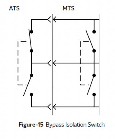
Transfer switch and bypass
isolation switch
Bypass-isolation automatic transfer switch
equipment is a manual bypass transfer switch in
parallel with an automatic transfer switch (see
Figure-15). The parallel connections between the
bypass switch and ATS are made with isolating
contacts such that the automatic transfer switch
can be drawn out for service and repair and power
is fed to the load through the bypass switch. The
bypass-isolation automatic transfer equipment
available from Cummins is the non-load break type
meaning there is no power interruption to the load
when power is switched from the normal path to
the manual ATS path. The manual ATS can also
provide an open transition transfer between the
sources when the automatic switch is not is use.
Voltage and frequency
Transfer switch equipment is available for a wide range of operating voltages at both 50 and 60 Hz. All types of
switches are available for low voltage (600 VAC and below) applications. Typical AC voltages are: 120, 208, 240, 480,
and 600. Also, single and three phase options are available.
The voltage chosen for the transfer switch will match the system voltage for the application, however, withstand and
closing ratings for the switch may vary with its voltage rating. This rating difference can affect the type of protection
equipment required upstream of the transfer switch.
Current rating
Transfer switches are rated for continuous current
which means holding the maximum value for
three hours or more. The continuous current rating
must be selected in accordance with the total
connected load requirements, sized essentially in
the same manner as the circuit conductors. Most
transfer switches can carry 100% rated current
at an ambient temperature of 40ºC. However,
transfer switches incorporating integral overcurrent
protective devices (for example: service-entrance
transfer switches) may be limited to a continuous
load current not to exceed 80% of the switch
rating.
Typically, the most used ampere ratings range
from 40 to 4000 amperes. Switch frame size
dictates the current rating range and the withstand
and closing rating (WCR). Most switches that
incorporate a switched fourth neutral pole utilize
a neutral pole rated the same as the phase poles,
but the manufacturer’s literature should be
referenced to confirm. It is recommended that fully
rated neutrals be used in applications containing
nonlinear loads, where the load induced harmonics
create substantial neutral current. The ampacity
of the switch must meet or exceed that of the
connected conductors.
Future load requirements should be considered
during the planning process and a transfer switch
with a continuous current rating equal to the total
of the anticipated future load should be selected
for the application.
Fault current capability
A fault downstream of the transfer switch will
result in a short circuit current flowing through the
transfer switch. High level of fault currents will
cause thermal and magnetic stress on the switch.
Since transfer switches are not designed to break
(interrupt) fault currents; therefore, they must
be protected by overcurrent protection devices
(OCPDs) on both sources.
To apply transfer switch equipment correctly
within its short circuit or withstand and closing
rating (WCR), it is first necessary to determine
the maximum available fault current from each
source at the switch location. Any potential
contribution from load sources (motors) must also
be considered. Typically, a utility source will have
higher available short circuit current, but generator
sources, particularly multiple generators, must
also be considered. The withstand and close rating
of the transfer switch must be matched to the
available fault current.
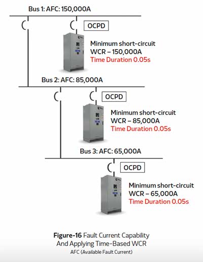
All transfer switch equipment is required (per
UL1008) to have short circuit ratings that are
Withstand and Closing Ratings (WCR), which
are expressed in RMS symmetrical amperes at a
maximum system voltage. The WCR is established
by testing only. Calculations of short circuit ratings
have no validity for applications. Rating can either
be time-based or specific OCPD (breaker/fuse)
based. Transfer switches with high time-based
short circuit WCR simplifies breaker selection for
protecting the transfer switch (see Figure-16).
Short-time fault
current capability
Transfer switch manufacturers can take the extra
step and perform the UL 1008 optional shortcircuit
short-time withstand and closing test and
subject the transfer switch to fault currents for
durations longer than what is listed in the UL 1008
standard. Short-time ratings are similar to WCR
ratings,except the duration of the fault is specified
by the manufacturer. For example, Cummins
PowerCommand® transfer switches short-time
WCR are rated to the maximum duration accepted
in the industry, which is 0.5s.
The difference between the short-time rating
and the WCR rating is that the short-time
rating requires that the transfer switch pass a
temperature rise test at rated load after the short
circuit test. What this means is that in order to
apply the short time rating the transfer switch
must still be functional after being subjected to
short circuit current at its short-time rating.
It is important to note that the short-time rating
must be withstand and closing rating. Transfer
switches listed as withstand rating only violate UL
1008 – as the rating is not a true short-time rating
and, per UL1008, shall not be accepted.
A typical application for a short-time rated transfer
switch is when is when it is applied downstream
of a UL1558 switchgear. Since UL1558 switchgear
can have a short-time rating of up to 0.5 seconds.
Another advantage of a high-short rating is
simplifying selective coordination strategies since
the transfer switch can carry that short-circuit of
up to 0.5s allowing downstream breakers enough
time to trip and localize a fault.
Selective coordination
NEC® defines selective coordination as
“Localization of an overcurrent condition to restrict
outages to the circuit or equipment affected,
accomplished by the choice of overcurrent
protective devices and their ratings or settings.”
Basically, it means that a fault is cleared by the
protective device nearest upstream from that fault
and does not result in unnecessary power loss
to other loads. Selective coordination is typically
achieved by setting the downstream breakers to
trip instantaneously and setting the upstream
breaker to have a delayed trip.
Selective coordination is required for emergency,
legally required standby and critical operations
power systems circuits per NEC®-2020, 700.32,
701.32, and 708.54.
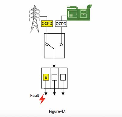
In the example shown in Figure-17, the OCPD on the
utility must trip after circuit breaker B, therefore a
time delay must be set on the utility OCPD. Time
delay setting of the utility OCPD depends on the
available fault current from the source and also on
device B trip curve characteristic.
For the duration of the utility OCPD time delay, the
transfer switch must be able to withstand the fault
and close into the fault. (See Figure-17).
Cable lugs and entry requirements
The typical lug options for transfer switches are compression, mechanical, or no-lugs buss stab only. The no-lugs option is typically seen on high amperage transfer switches, for example, above 1000 amps. All lugs are 90°C rated and accept copper or aluminum wire unless indicated otherwise on the manufacturer drawings. NFPA 70 Article 310 - Conductors For General Wiring outlines conductors ampacity ratings, mechanical strengths, insulations, and uses.
The cable entry areas are also documented on the transfer switch manufacture drawings. The typical entries are top or bottom. It is essential to consider the number of conductors and cable entry early in the design phase to avoid any potential delays or misalignment between, for example, a bottom entry and the concrete pad.
Enclosures
The standard enclosure meets requirements of the National Electrical Manufacturers Association (NEMA 250) and Underwriters Laboratories (UL 50E)
Typically, transfer switch equipment can be located most anywhere in a facility, even outside the facility. However, the location should be chosen to minimize potential damage due to acts of nature (rain, lightning, flooding), or vandalism. Typical NEMA enclosures are:
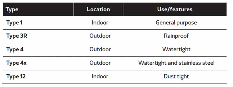
The enclosure choice is based on placement and environmental conditions. Transfer switches can be configured to include space heaters for outdoor installations where condensation could occur.
Summary
Transfer switches play a significant part in the power system as they are the last link between the power
sources and the loads. Since transfer switches are available in a variety of types, with a wide array of features,
selecting the appropriate transfer switch for a specific application requires a clear understanding of site needs
and application restraints. Some of the critical items to consider when specifying a transfer switch are: codes
and standards, transition type, number of poles, current rating, fault current capability (WCR), short-time ratings,
and grounding schemes. Whether the application is a simple standby power system in a warehouse, a large
emergency system in a hospital protecting the lives of patients, or standby service to a data center handling
millions of dollars in transactions, a careful consideration of the balance between cost, reliability and the quality
of power provided to critical loads is necessary to select the most appropriate transfer switch equipment.
About the author
Hassan Obeid
Sr. Technical Advisor – Power Systems

Hassan Obeid is a Senior Global Technical Advisor of Energy
Management Solutions at Cummins Power Generation
focusing on technical vision, business strategy and solving
a wide range of complex problems.
Hassan has been with Cummins since 2007 in a variety of
roles: power systems design engineering, project engineering
and applications engineering. Hassan has designed power
systems involving switchgear, controls, paralleling, transfer
switches, generator sets, renewable DERs, microgrids and
digital solutions. He has developed and conducted technical
power seminars on several topics and products involving
paralleling, grounding, power systems and controls.
Hassan received his bachelor’s degree in Computer Science
and master’s degree in Electrical Engineering from Minnesota
State University, Mankato.