Best Practices for Fire Pump Testing
Here is what you need to know to ensure your inspecting, testing, and maintenance of fire pumps is done correctly.
Fundamentally, fire pump performance tests fit into two categories. ITM standards require non-flow testing at frequent intervals and flow testing annually.
Facilities sometimes have odd or outdated fire pump flow test reports. ITM standards require annual performance testing of fire pumps. Facilities with fire pumps should have a fire pump performance test report on file that is less than 12 months old.
Whether you hire a third-party or conduct fire pump performance tests on your own, it is important to review and interpret the results each time a test is performed. Some third parties may not graph or interpret test result correctly or at all, and you could be left with indecipherable vital information. ITM standards instruct us to compare the annual test results to tests done the prior year. Unfortunately, it is always possible that the prior year’s results are flawed and do not represent a good baseline for comparison, creating even more confusion. You can find the criteria for characteristic fire pump performance in NFPA-20, the Standard for the Installation of Stationary Fire Pumps for Fire Protection.
Both centrifugal pumps and vertical turbine pumps have the same performance criteria. These types of fire pumps are tested for three specific proficiencies:
• The first test point is zero flow against a closed valve (called “churn”). The maximum head allowed is 140 percent of the rated value.
• The second test point is 100 percent of rated flow. Head should match the rated value.
• The third test point is 150 percent of rated flow. The minimum head allowed is 65 percent of the rated value.
On standard graph paper, when pump head (x-axis) and flow (y-axis) are plotted, the graph of a compliant fire pump is a gradually sloping curve that falls to the right. (See “Sample Fire Pump Curve” below.)
If you cannot find a previous flow test for comparison, an original fire pump curve makes a good baseline for performance comparison. From there, begin a file for all subsequent test reports. The original fire pump curve should be available from operation and maintenance manuals or the pump manufacturer.
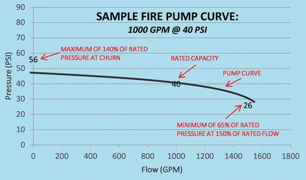
A compliant fire pump will have a churn pressure value below the first point marked (reading from left to right). The curve will pass through or very close to the second point, and the value will remain above the third point.
Related Topics: